With Docker 19.03 adding native support for GPU passthrough and Plex support for GPU transcoding being reliable and stabe, it's now very easy to get both working together for some super duper GPU transcoding.
I installed an NVIDIA Quadro RTX 4000 in my 2U server recently and after installing all the packages required and one flag to docker, Plex was able to use the GPU.
nvidia-driver
Firstly, we'll install the latest nvidia drivers for Debian buster. If you're on stretch or earlier, you will have to install the nvidia drivers manually. ffmpeg (which Plex uses for transcoding) requires at least 418.30 so check what distro provides if you aren't on Debian.
echo "deb http://deb.debian.org/debian buster-backports main contrib non-free" | sudo tee /etc/apt/sources.list.d/buster-backports.list

sudo apt update

sudo apt install linux-headers-$(uname -r|sed 's/[^-]*-[^-]*-//')
sudo apt install -yt buster-backports nvidia-driver libcuda1 libnvidia-encode1 libnvcuvid1
Once you got that done you will have to restart to not have the nouveau get in the way, then once you're back up you should be able to run nvidia-smi and see your GPU.
nvidia-docker
Now onto nvidia and Docker. Install Docker if you haven't and then we'll add the nvidia-docker gpg key and apt repository.
curl -sL https://nvidia.github.io/nvidia-docker/gpgkey | sudo apt-key add -
curl -sL https://nvidia.github.io/nvidia-docker/debian10/nvidia-docker.list | sudo tee /etc/apt/sources.list.d/nvidia-docker.list

sudo apt-get update

sudo apt-get install -y nvidia-container-toolkit

sudo systemctl restart docker
plex
With docker restarted, you should be able to run docker run --gpus all nvidia/cuda:10.0-base nvidia-smi and see the same output as before on the host. Next step is to add the --gpus all (see usage here) to your Plex container. Note that docker-compose does not have support for GPUs yet so you will have to do this with docker run for your container. For example, my plex is launched with a command similar to this:
docker run --name plex --restart unless-stopped --gpus all --network=host --env VERSION=latest --volume /plex:/config --volume /media:/media linuxserver/plex
Once Plex is up you'll want to go to Settings > Transcoder and enable Use hardware acceleration when available and Use hardware-accelerated video encoding. Now start watching something and make sure it's transcoding. You should then be able to check nvidia-smi and see the process and (mostly memory) usage. You should see something like this:
+-----------------------------------------------------------------------------+
| NVIDIA-SMI 440.82       Driver Version: 440.82       CUDA Version: 10.2     |
|-------------------------------+----------------------+----------------------+
| GPU  Name        Persistence-M| Bus-Id        Disp.A | Volatile Uncorr. ECC |
| Fan  Temp  Perf  Pwr:Usage/Cap|         Memory-Usage | GPU-Util  Compute M. |
|===============================+======================+======================|
|   0  Quadro RTX 4000     On   | 00000000:03:00.0 Off |                  N/A |
| 45%   74C    P0    86W / 125W |   2159MiB /  7982MiB |     11%      Default |
+-------------------------------+----------------------+----------------------+

+-----------------------------------------------------------------------------+
| Processes:                                                       GPU Memory |
|  GPU       PID   Type   Process name                             Usage      |
|=============================================================================|
|    0     32212      C   /usr/lib/plexmediaserver/Plex Transcoder    1501MiB |
|    0     32870      C   /usr/lib/plexmediaserver/Plex Transcoder     342MiB |
|    0     39082      C   /usr/lib/plexmediaserver/Plex Transcoder     302MiB |
+-----------------------------------------------------------------------------+
As you can see, 4K streams are quite memory intensive. They are 4x a 1080p stream which is 4x a 720p stream. GPU transcoding is primarily memory limited. Secondarily limited by number of streams: consumer cards are limited to 2 by nVidia. There is a patch to remove that limit though. Thirdly, you're limited by the nvenc and nvdec FPS limit. This website has lots of information comparing various GPUs and their transcoding performance.
If you don't see Plex in there, you'll want to look at Plex Media Server.log and look for any debug messages that might show why it's unable to use your hardware for transcoding. In my case I had 2 error messages: Cannot load libnvidia-encode.so.1 and Cannot load libnvcuvid.so.1 which is why I you install those libraries earlier.
Enjoy your sweet GPU transcoding!
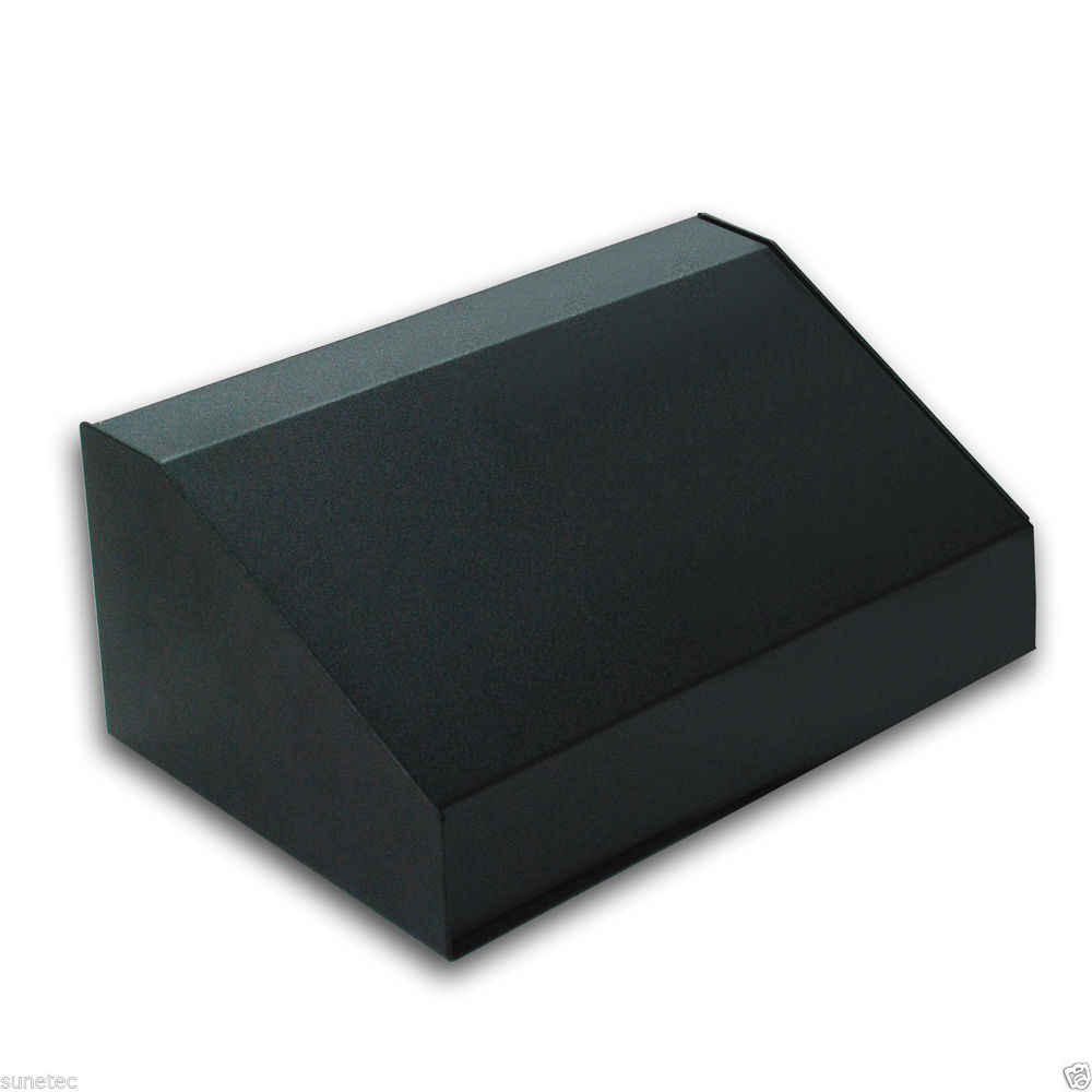
 Sloped
 Rear[/caption]
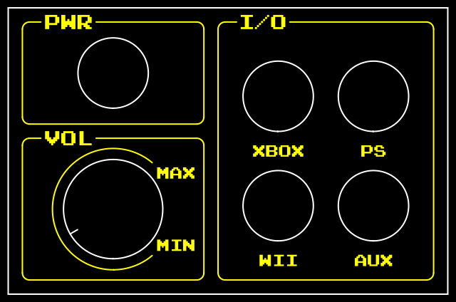
 Front
Front